Similar
Locomotive engineering - a practical journal of railway motive power and rolling stock (1897) (14574921679)
Summary
Identifier: locomotiveengine10hill (find matches)
Title: Locomotive engineering : a practical journal of railway motive power and rolling stock
Year: 1892 (1890s)
Authors: Hill, John A. (John Alexander), 1858-1916 Sinclair, Angus, 1841-1919
Subjects: Railroads Locomotives
Publisher: New York : A. Sinclair, J.A. Hill (etc.)
Contributing Library: Carnegie Library of Pittsburgh
Digitizing Sponsor: Lyrasis Members and Sloan Foundation
Text Appearing Before Image:
ime system for railway, telegraph andpostal work, making two countries whichhave fallen into line—Italy being thefirst. It is not compulsory in either coun-try, but is adopted to simplify railwaytime-tables, and for convenience gener-ally. It clearly does away with mistakesin A. M. and P. M., and is the rationalmethod, which seems likely to be adoptedgenerally when time has rolled around afew more centuries—if not before. $ i $ A locomotive engineer, writing fromApizaco, Mexico, says that it is the prac-tice on the Mexican & Vera Cruz Rail-way to fit up side rod brasses when therods are at the top or bottom quarter.The breakage of side rods is reported tobe very frequent, and several severe acci-dents to enginemen have happened re-cently. Our correspondent seems to at-tribute these accidents to the rods beingkeyed out of proper length. Accordingto our correspondent, there are a greatmany shop practices in vogue on thatroad which ought to be changed. LOCOMOTIVE ENGINEERING. eis
Caption:
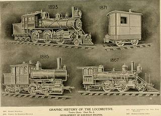
GRAPHIC HISTORY OF THE LOCOMOTIVE. Twelve Charts. Chart No. 8. DEVELOPMENT OF SUBURBAN ENGINES.
Text Appearing After Image:
LOCOMOTIVE ENGINEERING. 617 Special Drilling Machines. Two very convenient and handy littletools devised by Mr. Pulaski Leeds, sup-erintendent of motive power of the Louis-ville & Nashville Railroad, are in use inthe shops on that line, in the shape ofmachines for drilling jobs that cannotbe well handled at the drill-presses. In the illustrations, Fig. I represents aportable machine for drilling in cither ahorizontal or vertical plane. The wholething is contained in a space 18x24 are drilled without sac rificing the wear-ing surface of an eccentric. Fig. 2 is a drill u ed foi horizontal workonly, in direct connection with a dullspindle from which it is driven by means ofthe shank secured in thedrivinggears. Thefeed is had in this case by the hand wheelshown, the machine being clamped to thedrill press table when in operation. The same drill in all general featuresas the above is shown in Fig. 3, which hasmultiplying gears, and is fitted to a base angular po ition with reference to
This image dataset is generated from our world's largest public domain image database. Made in two steps (manual, and image recognition), it comprises of more than 35,000 images of all types and sizes - an astonishing number if keep in mind that the total number of steam locomotives ever built was just one order of magnitude larger. All images are in the public domain, so there is no limitation on the dataset usage - educational, scientific, or commercial. Please contact us if you need a dataset like this, we may already have it, or, we can make one for you, often in 24 hours or less.
Tags
Date
Source
Copyright info


